
ATCA World is a Global Publication of e2mos
Unmatched Global Market Coverage
ATCA - AMC – MicroTCA
Most Powerful STANDARDIZED Embedded Computing Systems
Open Modular Multi-vendor HPC Architectures for Hi-end Blade Computers
ATCA (or AdvancedTCA) Overview
High Availability Five Nines (99.999%) and Six Nines (99,9999%) Redundant Systems • NO Single Point of Failure
For Critical Applications and Sophisticated Systems like: Telecom - Mil/Aero - Industrial - Physics - Research
ATCA stands for: Advanced Telecom Computing Architecture (when introduced in 2001 first focus was Telecom)
ATCA is The ONLY Standardized Platform for Carrier Grade Telecom System, for Large & Medium Networks (see Mobile Networks in the menu above)
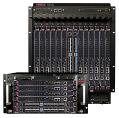
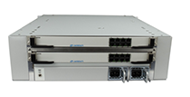
ATCA Redundant System
For Large TELCO Networks
Front Side - 6 & 14 Slots
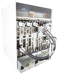
ATCA Redundant System
14 RTM’s (Rear Side)
Rear Transition Modules
More Connectivity and Less Cables
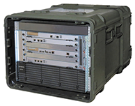
Military Mobile
ATCA System
6-Slots
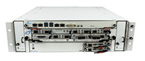
3U ATCA Hybrid Chassis
with 8 AMC’s and
2 ATCA RTM’s
(RTM = Rear Transition Module
The Advanced Telecom Computing Architecture (AdvancedTCA®) specifications, denoted PICMG 3.X, are a series of PICMG specifications, designed to provide an open, multi-vendor architecture targeted to requirements for the next generation of carrier grade communications equipment. This series of specifications incorporates the latest trends in high
speed interconnect technologies, next generation processors and improved reliability, manageability and serviceability.
AdvancedTCA, also known as ATCA, is the first open architecture that provides an extremely sophisticated and robust system management architecture that enables High Availability
systems that keep running in the event of individual component or sub-system failure. This also enables “on-the-fly” software upgrades while the system is operating.
The original AdvancedTCA specification was released in January of 2003 and has been adopted by many of the top telecommunication equipment providers. It has expanded its reach into non-carrier grade environments where high processor and I/O density coupled with high system bandwidth are required.
ATCA is the ONLY Standardized Platform for Carrier Grade Telecom Systems, it is the most widely used open standard for global telecommunications infrastructure and is becoming so for a variety of critical military applications. AdvancedTCA is also employed in large-scale physics experiments and ruggedized applications in the military market.
Companies participating in the AdvancedTCA effort have brought a wide range of knowledge of the industry. They include telecommunications equipment manufacturers, board and
system level vendors, computer OEMs, software companies and chassis, connector and power supply vendors.
The specifications provide enough information to allow board, backplane, and chassis vendors to independently develop products that will be interoperable when integrated together. Details include board dimensions, equipment practice, connectors, power distribution and a robust system management architecture that can be used independent of the switch fabric
link technology. Interoperability of system components from different manufacturers is tested regularly through an on-going series of PICMG-sponsored Interoperability Workshops.
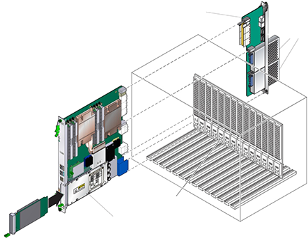
The AdvancedTCA community has recently completed and released of a fairly major enhancement to the core ATCA standard. This new specification is known as “PICMG 3.7” or “ATCA Extensions.” It expands the packaging definitions to include dual sided shelves, where ATCA boards can plug into either the front of the back of a double-deep rack and interconnect
through the backplane. In addition to this, the Extensions specification also allows for something called Extended Transition Module (ETM) that is essentially a front board-sized circuit
board that connects to a front board via Zone 3, much like a standard Rear Transition Module (RTM. There are many variations of interconnects allowed, but Figure 1 below gives
a general idea of the concept.
Importantly, PICMG 3.7 provides a much more detailed definition of, and support for,
double wide modules than the original specification. These can support multiple processors,
bigger heatsinks, cheaper full height memory modules, and multiple disk drives on
a single assembly if desired. PICMG 3.7 also defines requirements for typical data center
environments in addition to the telco central office. Double wide modules can support
up to 800W of power dissipation if the shelf is built for that. AC as well as traditional
-48VDC power environments are also supported.
The PICMG 3.1R3.0 – 100GbE ATCA specification has also been ratified. Driven by
the need for higher bandwidth in mobility, video and security, this effort provided capacity
improvement to the ATCA platform by incorporating 100Gb backplane Ethernet. Backward
compatibility has been maintained. PICMG 3.1 R3.0 updated the PICMG 3.1 specification
to incorporate 100GBASE-KR4 (NRZ) Ethernet signaling with full simulation/characterization
studies to ensure compliance.
AdvancedTCA now supports IPv6 Addressing Protocols
Key Benefits and Features
- AdvancedTCA provides the high availability necessary for central office applications which
often require European Telecommunication Standard Institute (ETSI)
and Network Equipment Building System (NEBS) compliance. - Each chassis can accommodate up to 16 slots (23” width) or 14 slots (19” width)
to offer scalable capacity up to 10 terabits per second. - Includes hot-swappable, managed and redundant fan units to cool blades which
can dissipate 400 Watts per slot. - Redundant -48 VDC power infrastructure compatible with global telecom standards.
- The mid plane design allows usage of Rear Transition Modules (RTM) for I/O connectivity to the companion front board blade.
This is popular in central office telecom applications where it is desirable to be able to change computer modules without disturbing wiring. - Blades are interconnected redundantly in star or mesh fabric topologies via a base interface and via an optional fabric interface.
- The base interface and higher speed fabric interface provide connectivity across the slots allowing separation of control plane processing from
higher bandwidth user plane data. - Supports multiple switching fabric interfaces as defined in standards PICMG 3.1
(Ethernet and Fiber Channel) through PICMG 3.5 (Serial RapidIO). - High levels of modularity and configurability can be achieved through the use of Advanced Mezzanine Cards (AMC)
as defined in the PICMG AMC family of standards. - Shelf management monitors and controls blades and other Field Replaceable Units (FRUs). It also controls power,
cooling, and interconnection across the system enabling
enhanced functionality - The shelf management system can retrieve inventory information and sensor readings as well as receive
event reports and failure notification from any FRU. - The shelf management also performs basic recovery operations such as power cycle and reset of any managed entities.
RTM
Rear Transition Modules
for I/O connectivity to
the companion front board blade
ATCA CPU Blade with One AMC Slot
Increasing Flexibility - Reducing inventory of CPU
ATCA Chassis
Backplane
Additional
Storage
ATCA Carrier Blade
with 4 AMC Slots
500+ Functions available
including multiple disk
drives for Storage
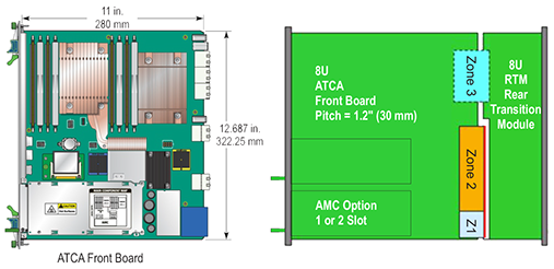
All ATCA Boards (Blades) are 8U Form Factor
- Board Front Board size 8U x 280
- Rear board (RTM) size 8U x 70 mm
Connects directly to Front Board - Board width 6HP (1.2”)
- Alignment/Key pins
- Zone 1: Management and Power
- Zone 2: Base Interface and Fabric Interface
- Zone 3: Interface to RTM size and connectors
Note:
- The RTM connects directly to the ATCA Blade via Zone 3
- The System Backplane (in red in the drawing) is for Zone 1 and Zone 2
Publisher: www.e2mos.com l Contact: mgt@e2mos.com
ATCA World is FREE - Direct Download - No Login - No Password
Our 6 Magazines & Dedicated Web Sites are addressing the Key Hi-Tech Markets Worldwide - CLICK on the Logo’s